Mud agitator Description of agitator
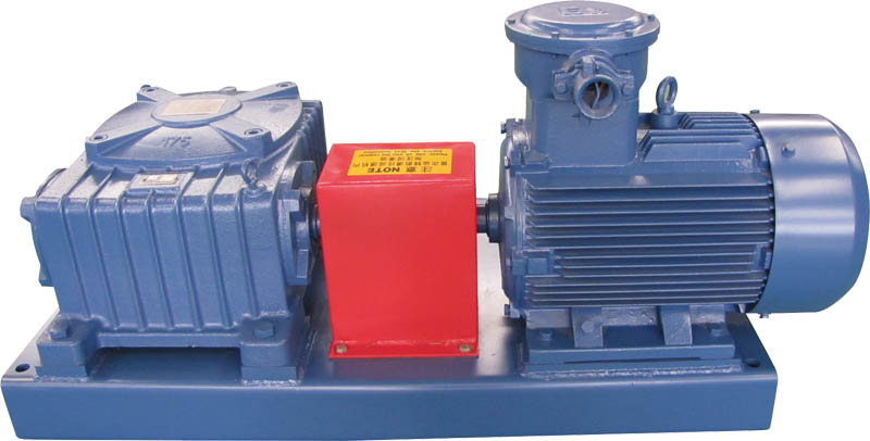
The reducer of agitator is designed on the basis of Archimedes worm gear, with worm being set on the left. The motor and the reducer are connected using double offset elastic coupling, and the reducer output shaft and the mixer shaft are connected using fixed type flange coupling.
Table 1 Major technical parameters
Model of agitator | Model of motor | Motor power (kw) | Impeller diameter (mm) | Rotation speed of impeller | Weight Kg | |
NJ5.5 | YB2132S-4 | 5.5 | φ760 | 1 | 71 | 392 |
NJ7.5 | YB2132M-4 | 7.5 | φ760 Ф760 | 2 | 71 | 418 |
NJ11 | YB2160M-4 | 11 | φ850 Ф500 | 2 | 71 | 472 |
NJ15 | YB2160L-4 | 15 | 2 | 71 | 535 | |
NJ18.5 | YB2180M-4 | 18.5 | φ1000 Ф500 | 2 | 71 | 640 |
NJ22 | YB2160L-4 | 22 | φ1000φ760 | 2 | 71 | 640 |
Major technical performances and parameters:
1、Model: NJ Type;
2、Power of motor: 5.5-18.5kw;
3、Structural form: horizontal installation;
4、Operating environment:- 30℃~50℃
Humidity: 95% Elevation :1000 m
5、Principal structural form
Installation, use and maintenance
4.1 Process of field installation
4.1.1 Firstly place the paddle and connecting rod in the tank, then position the main machine of agitator. Before fixing the main machine, it is necessary to confirm that the base is horizontal and stable.
4.1.2 To reduce noise, it is feasible to add a rubber in thickness of 5mm between the base and the fixed surface.
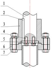
4.1.3 Connect the connecting rod with the output shaft of reducer for installation.

1.Transmission shaft of reducer
2.Key
3.Upper coupling
4.Anti-breaking bolt
5.Stopper
6.Lower coupling 7.Fastening bolt
Note: Equipment factory coupling has been installed location, at the same time, prevent to take off the bolt is installed, users only need to install the coupling
4.1.4 Pull through and fix the upper layer of paddles from the bottom of agitator arm, and pull through and fix the lower layer of paddles from the bottom of agitator arm.
4.1.5 After tightening all the bolts, carefully inspect whether these bolts have been tighten.
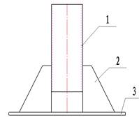
4.1.6 The installation of lengthened agitator with centering mechanism

1.Centralizing pipe
In the process of installation, firstly insert the agitator arm into the centering pipe, then fix the agitator arm and finally fix the centering structure to guarantee the verticality of agitator arm, for fear that the reducer may be damaged due to inclination.
4.2 After installation of agitator, rotate the coupling by hand, which shall have no blocking/jamming phenomena.
4.3 At the time of field use, firstly open the venting screw cap and fill in N100 - - - N320 lubricating oil (GB / T 3141 - 1994). If the ambient temperature is relatively low, it is necessary to adopt the lubricating oil with lower viscosity. The reducer shall be added with lubricating oil with the same brand as original, and it is not allowed to mix lubricating oils with different brands. It is allowed to mix the lubricating oils with same brand but different viscosities for use.
4.4 For the reducer, it is necssary to charge the lubricating oil to the middle line of oil scale and to control suitable fuel charge, becuase too much or too little fuel charge will lead to damage to reducer. It is feasibel to refer to the reserve quantity of lubricating oil listed in Table 3.
Table 3 The reserve quantity of lubricating oil used for reducer
Model | NJ5.5 | NJ7.5 | NJ11 | NJ15 | NJ18.5 |
Oil quantity ( L) | 14.2 | 14.2 | 16.7 | 16.7 | 27.2 |
4.5 After the power supply for motor is properly connected, make trial run. The rotation direction of motor shall be consistent with the arrow identification on the protective cover, or it is necessary to adjust the wiring connection phase sequence of motor.
Prior to starting, please confirm that personnel have been far from the paddle, so as to avoid personal injury caused by rotation of paddle! |
4.6 After power-on, it is necessary to observe the operation for 5 minutes. After confirming that there is no abnormal sound, it is allowed to put the motor into service.
4.7 The replacement cycle of the lubricating oil of reducer
When using a new reducer for the first time, it is necessary to change new lubricating oil after operation for 100 hours. In the later use, make periodical inspection on the quality of lubricating oil. It is necessary to change at any time the lubricating oil that has included foreign substance or become aged and degenerative. However, in general cases, for the reducer used for long-term continuous operation, it is necessary to change the lubricating oil once for every 3-4 months or 1500 operation hours.
If obvious rise in oil temperature, oil temperature exceeding 95℃, quality reduction of lubricating oil as well as abnormal noise are discovered in the process of working, it is necessary to stop using the lubricating oil and inspect the cause. If said phenomena are caused by the gluing of tooth surface, it is necessary to make repair, remove the fault and change the lubricating oil before using the equipment again.
4.8 Maintenance of motor
4.8.1The motor shall be subject to periodical inspection and clearing; dust may not be accumulated on the motor casing, and it is not allowed to use swivel to spray the motor for clearing.
4.8.2 When the motor is operating, the allowable temperature for bearing may not exceed 95℃. It is necessary to make inspection once at least every 2500 operating hours of bearing. Upon detection of the deterioration of bearing grease, it is necessary to replace the grease in time; prior to replacement, it is necessary to clean the bearing using gasoline. The lubricating grease shall be ZL3 lithium base grease. The fuel charge is 2 / 3 of the net volume of bearing room.
4.8.3 At the time of disassembly of cable, it is not necessary to dismantle the rubber pad, for fear that the explosion insulation performance of junction plane may be affected.
4.8.4 In case the motor is exposed to moisture, it is necessary to conduct drying process, with temperature not exceeding 120℃.

 Tel:Whatsapp
 Tel:+86-18303261131
 Email:fortunel@fdpetrol.com
 Address:Xinhua Park,Economic Development Zone,Cangzhou City,Hebei Province,China.